Explanations
In order to use this application it is essential to input valid parameters that you have obtained from one of the following sources:
- a testing programme, performed using good quality testing equipment and processes on a representative sample. This can be from, for example, a prospective equipment vendor an independent or in-house testing laboratory
- based on experience (say from a similar operation) or provided by a subject matter expert.
Testing requirement
Filtration and thickener testing are often performed together. In any case, is
Summary
- Quality, filtration tests should be performed under representative conditions.
- Ideally, these conditions should cover a range of slurry solids content and possibly composition
- Testing should be performed for:
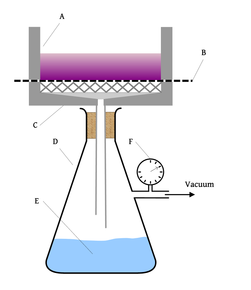
- Vacuum
- dip tests (to represent, for example, vacuum disc filtration)
- buchner tests, representing vacuum belt filtration
- Pressure
- with
- using a representative range of filter media (including filter cloths and ceramic media, if part of the selected range of alternatives)
- Vacuum
In order to gain a This page describes how to use the calculator, giving the expressions used in the calculator.
Process Design Criteria
The inputs on this tab provide the input for later calculations. You may also choose to use these tools for ad-hoc standalone calculations.
Slurry Parameters
It is essential to complete this section for the rest of the calculator to work. Here you are finding the slurry parameters for the feed to the filtration plant and will typically be thickener underflow. To use it, first select one unknown parameter. In most cases, this will be Solids Density, as the others can be found to a good level of accuracy very simply:
- Liquid Density - decant a known volume of liquid from the slurry (this may be after settling or filtration) and measure the weight
- Slurry Density - weigh a known volume of well-mixed sample
- Solids content - weigh a sample of well-mixed slurry before and after drying. It is important to note that this should be the solids content expected to arrive at the filtration plant, and will be thickened.
In other cases, Solid density may be measured directly using Gas Pycnometry. In all cases, you should take care to avoid entraining air in samples (for example through vigorous mixing).
The fourth parameter is calculated using a rearrangement of the following expression: 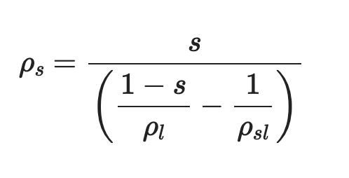 Where:
- 𝜌𞁩 = solids density (kg/m³)
- 𝜌ₗ = liquid density (kg/m³)
- 𝜌𞁩ₗ = slurry density (kg/m³)
- s = solids content in slurry (% w/w) If you do not have access to a sample then you can, with caution, use sensible defaults. You should consult with experts in filtration. It should then be a priority to obtain sample(s) to find these parameters.
Design Throughput
It is safe to use the daily mill throughput for Daily Throughput. You can take future scenarios, for example plant expansion, into account. This input is metric tonnes per day of dry solids. The Expected Availability field refers to the overall availability of the tailings filtration plant, taking into account planned maintenance. It is crucial that this be discussed with experts from equipment vendors or engineering companies.
You can be as descriptive as you like in the Comments for Report box. If you are going to use this tool fully and produce the downloaded report, this can be read by anyone that you send this file to, for example project colleagues, vendors, engineering support. Example inputs:
- “slurry parameters updated after test-work completed”
- “based upon information from NI 43-101 Technical Report on…”
Sense checking filter capacity
This section of the tool takes the slurry parameters and calculates the volume (and hence tonnage) from operational parameters that you can obtain from test work or operational experience. These expressions are true, not open to interpretation, and have the basic form: 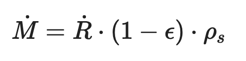 Where:
- Ṁ = solids throughput, metric tonnes per hour dry basis (tph)
- Ṙ = cake/ paste volumetric throughput (m³/h)
- ε = cake porosity (-)
- 𝜌𞁩 = solids density (kg/m³)
However, in real-world operations there are a number of factors that may affect the daily capacity of a filtration plant:
- filter medium blinding, or clogging
- Non-producing time
- unexpected shutdown due to mechanical failure
- planned maintenance or cleaning
At present there are 4 broad types of filtration device included in the tool. Perhaps the most useful way to categorise filtration devices used in tailings (and other mineral concentrate) duties is:
- what is driving the dewatering process, generally:
- vacuum behind the filter medium (so that atmospheric pressure drives liquid through the cake and filter medium)
- pressure
- whether the units operate in Continuous or Batch mode.
| Vacuum | Pressure | |
|---|---|---|
| continuous | belt disc | hyberbaric disc |
| batch | filter-press | |
The calculation principle for determining a specific capacity (in other words, mass of solids per unit filter area). Therefore the next step is to determine Volumetric throughput of cake.
Calculation of cake volume (per m²) for batch filtration devices (e.g. Filter-Presses)
Here, we calculate: 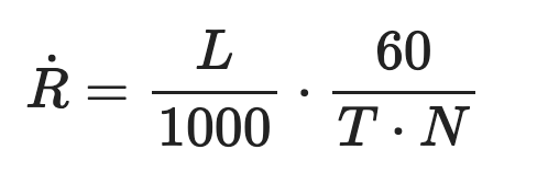 Where:
- Ṙ = cake/ paste volumetric throughput (m³/h)
- L = cake thickness (mm)
- T = total batch time (min)
- N = number of filtration sides (-)
the Inline** Inline math: TKTK (Trial equation)
This image links to google.com 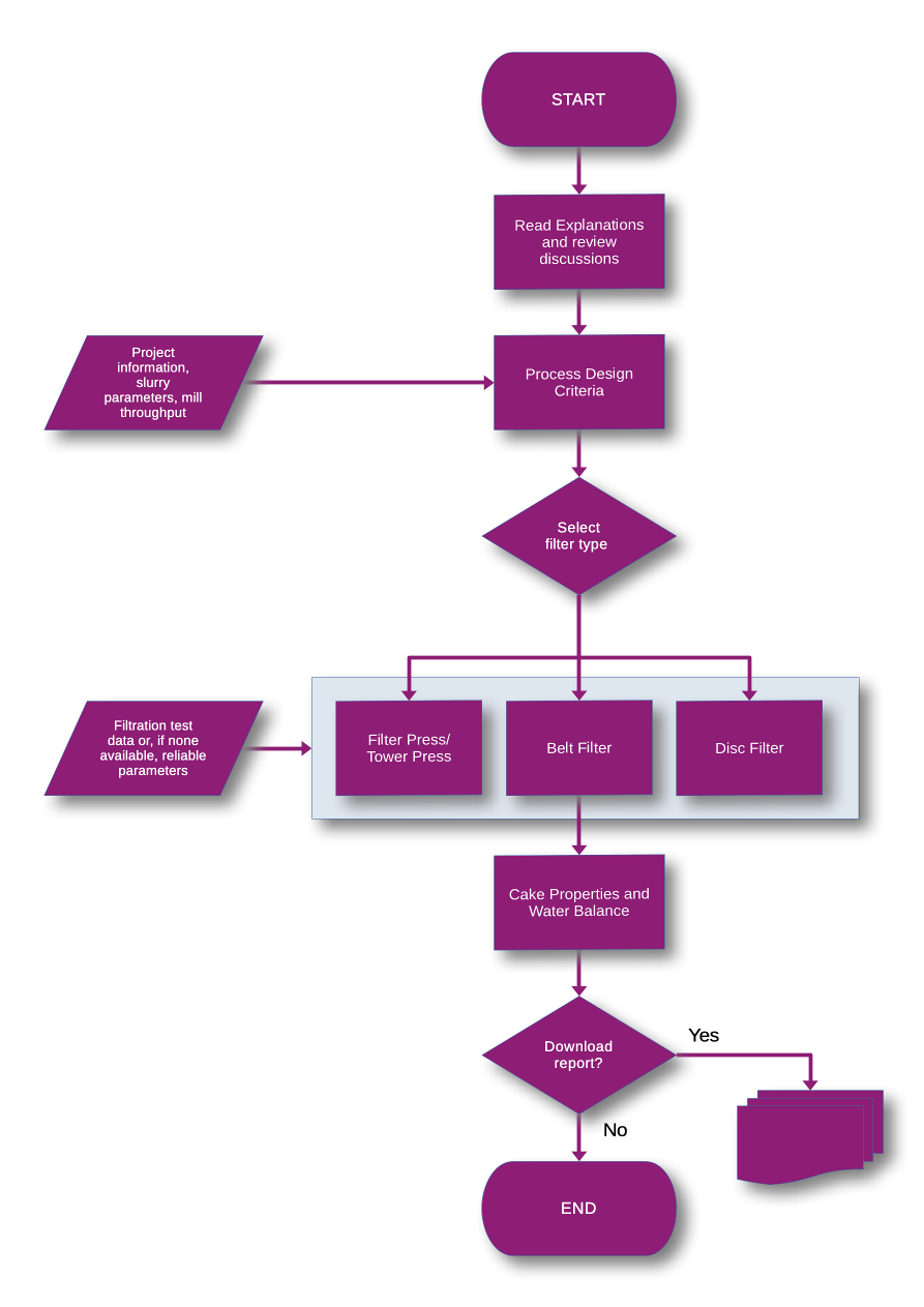
- Display math:
- Code Block
code lives here
testing.
link to Summary TKTK attempt to link to a subheading in this document