Disc Filters
Vacuum disc filters have filtration elements (sectors) connected as a series of discs on a rotating shaft that is connected internally to a vacuum circuit. As the shaft rotates, the sectors enter a slurry trough, filter cake forms on the elements and, after the sector has left the slurry, and the sector is still drawing vacuum, the filter cake drains/dries. 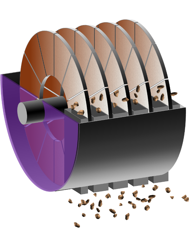 Slurry is fed continuously into the slurry trough, controlled by a feed-valve/ level sensor or with an weir overflow sending surplus slurry back to the feed tank.
Dewatering
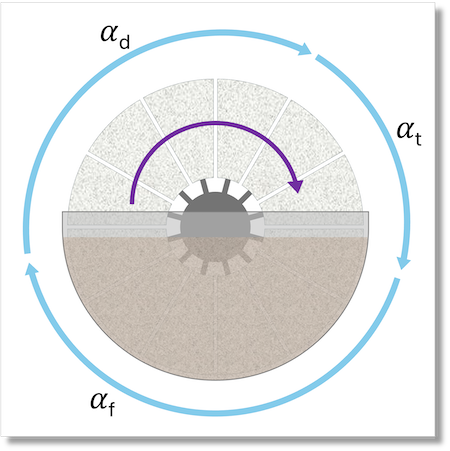
Below we follow one rotation for a single sector in more detail.
- Cake formation Initial cake formation and filtration occur during the sector’s time in the trough. The cake thickness (one of the parameters that you will input to the calculator) is determined by the time that the sector is in the trough, the vacuum level, filter media resistance and cake resistance. This portion of the rotation is the forming angle, .
- Cake draining/ Air drying After leaving the slurry, the sector will continue towards cake discharge. During this time, the liquid in the pores of the cake will continue to be be drawn into the vacuum circuit and, in a conventional (cloth) filter be displaced by air passing through the cake. This is the drying/drying angle, .
- Cake Discharge After the cake formation and drying/ draining phases of the rotation, the cake is discharged. This may be by simply removing vacuum from the sector (using a blocking bridge in the control valve), providing a short back-pulse of air, using scrapers or a combination of the above. The cakes fall into a chute that passes through the slurry trough. This, together with the part of the rotation where no cake is forming or draining, is the technical angle, .
The sector passes back into the slurry trough and Steps 1. to 3. are repeated, with cake passing into the cake chutes continuously.
The percentage of the cycle that the sector is in each of these phase is affected by the following:
- the depth of the slurry in the trough, which can be varied in operation
- the design of the control-head (see below), the interface between the sectors and the vacuum circuit (and, optionally, the back-pulse air)
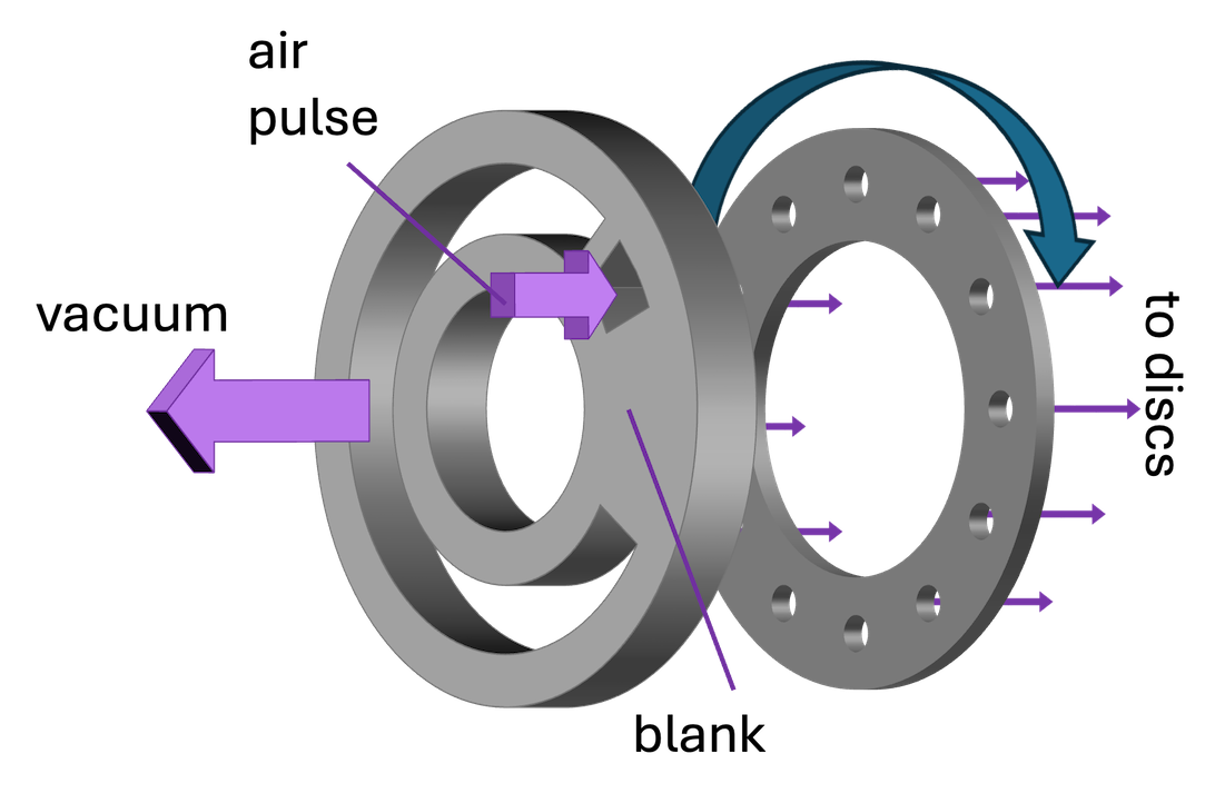
The control head is fixed and will connect each sector to (for example) the vacuum circuit, (optional) back-pulse or blank sections as the shaft rotates.
Filter media
The sectors may be covered in a woven filter cloth, in which case air can pass relatively freely through the filter cake and into the vacuum circuit.
Ceramic capillary action disc filters are a variation in which the capillaries in the micro-porous ceramic membrane allow water but, crucially, not air to pass through. This means that the large vacuum pumps needed by conventional vacuum filters (which would draw a large amount of air through the cake) are not needed, giving an significant reduction in power consumption. Ceramic disc filters generally use a finely adjusted scraper for cake discharge, since the rigid disc can be made to rotate within a very tight tolerance.
Testing
The most suitable test equipment is a dip-testing device, similar to the one below. 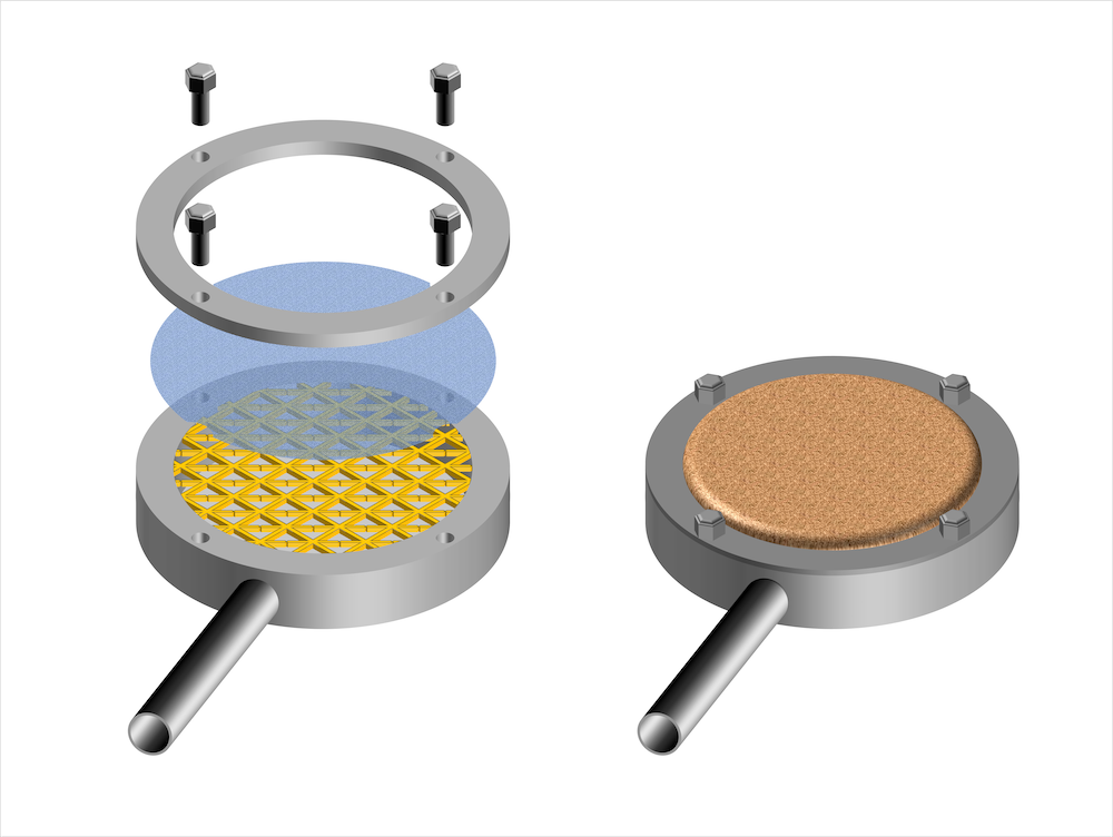
A basic test proceeds as follows:
- Connect the dip-tester to a vacuum circuit
- Set the blocked vacuum level (for example close a valve and measure the vacuum in the receiver)
- Put the dip-tester into a bucket of suspended slurry and open the vacuum valve
- After a measured time, remove the dip-tester from the bucket and keep the vacuum valve open for cake draining/ drying.
- Record:
- time that the dip-tester was in the slurry with vacuum (s)
- cake draining/ drying time (tester out of the slurry with vacuum still applied) (s)
- cake thickness (mm)
- observations about the cake
- cake moisture (% w/w)
To obtain the parameters necessary for the filter plant calculator with a laboratory test, you will need to estimate the proportion of the overall cycle that each sector will be in each of the phases, as well as the rotational speed. A test approach might look like this:
- Investigate the cake formation time.
- Assume a ratio between the times for cake formation and air-drying/draining.
- Perform tests
Worked example
Using a dip-tester, you find that a 10 mm thick cake forms after 15 seconds with a vacuum of 50kPa. You assume that , the cake forming angle, is 100o, and the technical angle is 45o. If you are working with an equipment vendor, you should check. The total cycle time will be: = 54 seconds.
And the rotational speed, therefore: = 1.11 rpm
Then the drying angle, will be: = 215o
And the drying time, td, therefore: = 32 seconds.
You can therefore perform a test with the following times:
- 15 seconds cake forming (tester in slurry with vacuum on)
- 32 seconds cake draining/drying (tester removed from slurry with vacuum on)
You would then select Disc filter in the Validate Filter tab of the Filter Plant Calculator and input Cake Thickness 10 mm and Disc Speed 1.11 rpm, with the following result (assuming Cake Porosity of 60% v/v and Solids Density) of 2730 kg m-3: 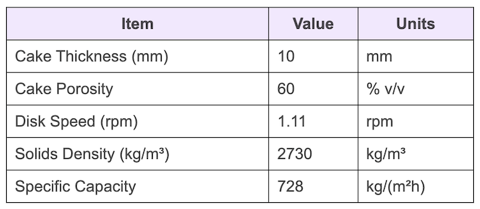
You can then input the measured Cake Moisture in the Water/Cake tab. This will show the (maximum) Water Recovery and generate a Cake Phase Volume chart.
Units and conventions
| Symbol | Name | Units |
|---|---|---|
| cake forming angle | degree | |
| cake drying/draining angle | degree | |
| technical angle | degree | |
| cake formation time | s | |
| cake drying/draining time | s | |
| rotational speed | rpm | |
| total time for one rotation | s |